Using this code means that you adhere to our open source agreement. Is provided as is and we accept no responsibility for damage to your equipment, hardware or software. It has been tested to work with the RELAY16 module from Numato Labs.
https://app.box.com/s/38y1qij2ivma8eo455ia
You may need to rename the file extension to .zip
Once you have the file downloaded, extract it and open it in Visual Basic 2010. Personally I used Visual Basic 2010 Express.
Tuesday, July 16, 2013

Monday, July 8, 2013
Measuring it up!
Time has come! Final assembly (minus Solenoid valves *insert "Awwhs here", which aren't set to arrive until at least September) is well underway. During the final week in the school workshop, I got the prototype down and learned a few things along the way, including: your math may be impaired by heat (because 11+0.75+0.75 = 14 right?). More lessons learned below.
 Thornlea's existing launch system (the while triangle with all the stickers on it). You can see the Kel-Accel Race timing system as well.
 A view of the Thornlea workshop and the first section of the 64' long modular track, which can be reduced in length down to 16' + an 8' run off. (an apostrophe (') means a measurement in feet)
 Deciding how I am going to mount the race tree. At the beginning I considered doing a flip up unit, however the thought of this being a school environment caused me to re-think that idea.
 A quick measurement of how high the existing unit was before I dismantled it.
 After removing the existing launcher I realized that there was an extra 0.5" spur out the back. (a quotation mark (") means a measurement in inches).
 A quick measurement deemed the existing timing system to sit 12" away from the back of the track. After talking with the teacher, it was deemed a good idea to integrate the mounting of it into the new launcher.
 The Prototype, after much cutting and hot glue, it's finally complete. The top of the unit will hinge upward to allow the cars to be staged.

 A quick test fit, and seeing where the provisions for the Race timing unit would be.


 The 45 degree piece at the back top that will hinge the top. This is where I learned that it helps to pay attention in math class. Luckily my math teacher dropped by right in time for me to ask for help on the calculations. in the end, I missed by a little bit, however another cut on my table saw at home should solve that issue.
 A view of how the 45 degree piece would fit into the final design.
 That's all for the shop folks. It's working at home from here on in.
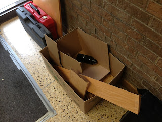 The box of stuff I took home to build this enclosure. The tools in the top left of the photo are provided by Prime Mechanical Co. (of Toronto, Ontario, Canada). I would like to thank them as well for providing the hard drive space to hold all the drivers and software for this project in addition to providing tools for assembly.

 As you can see from this view, I've attached both sides however have not yet cut or attached the acrylic glass.


After cutting out some pieces and seeing how I would do final construction. this mock-up was at a point where I thought I would make the top out of acrylic glass, once again, it was deemed not a good idea in a educational environment to have such a easy to break material in a place where someone could potentially fall on top of it. The frame wood was then re-purposed for the side acrylic glass windows.


The final width of the launcher is 13"

A view of the inside of the launcher, the sides will be acrylic glass, that was spectators can see without taking a huge blast of compressed air in the face.


When I got home, I went right to work assembling the pieces I already had. The solenoid plate measures 13"W x 10"H. The 45 degree piece is a little more than 0.75" on the edge... which causes a problem which I will have to solve.

Replacement GPIO Module
The new Replacement GPIO32 module from Numato has arrived! I must express my sincere gratitude to Numato Labs for providing a replacement via express UPS. I love it when companies stand behind their product.
 Arrived in a mighty brown UPS bag, with the Numato package inside.
 The new module nicely bubble wrapped for protection.
 The new module inside the sealed Anti-static bag.
 After grounding myself, I extracted the GPIO and tested it in HyperTerminal to see that it worked!


Sunday, June 16, 2013
Update 16/06/13 Controllers
UPDATE 16/06/13: The making of the acrylic launch buttons/controllers has been interesting, using a piece of 1" Acrylic rod cut 4" long and drilling a hole vertically through it. I will be using 4-wire Telephone extension cables to connect the controller (2 wires for the switch, 2 for an LED so that users can confirm that the controller is plugged in properly).
As you can see here, I kinda messed up the first one

The trick according to my teacher was to go slower.
The next one I did was essentially almost perfect
and the final one was a pain and I broke the drill press at school in the process.

But in the end, I succeeded
 Lessons learned: drill slowly (maybe only a couple cm at a time, and allow 5-10 minutes to cool down, don't rush it), if your going to cool it with water, do it from the beginning or don't do it at all, otherwise it separates (as you can see halfway through the second one), never stop the bit inside the acrylic or thats the end of it unless you can pry/spin it off, lastly, it's important to have an emergency stop, that saved my butt more than 4 times on this project.
As you can see here, I kinda messed up the first one

The trick according to my teacher was to go slower.
The next one I did was essentially almost perfect
and the final one was a pain and I broke the drill press at school in the process.

But in the end, I succeeded

Saturday, June 15, 2013
Wrap up of working at school
With Summer Vacation around the corner, I have to face the reality that this is no longer a school project and have taken it under my wing as what is probably the most expensive/advanced personal project I've ever done. I would like to take a moment to post from my facebook: https://www.facebook.com/cal920c/posts/10152952895525512 :
As mentioned above, I'd like to thank Numato Labs for their ongoing support of this project. I will soon have some more pictures, this time of the launch controllers (the boards haven't done much as the GPIO is DOA). In addition once the code for the Relay is done (without the GPIO), i'll post that separate from the final code for anyone who doesn't wish to use the GPIO with their unit. Right now as stated were having some Operating system compatibility issues.
Modelcarlauncher.blogspot.com hit another snag today, the program it seems is incompatible with Windows Xp (SP2 & SP3). Working with the programmer (unsure if he wants to be named) on a solution, or if we should just write it in the manual. With exams right around the corner, I hope this thing moves more smoothly from now on! gotta thank Numato Lab for helping me diagnose problems and for the boards. Without them over 50% of this project would've been impossible. thanks to my consulting teams as well. Hopefully this thing will be ready for final delivery to Thornlea S.S. (my school) by September. Monday and Tuesday I'll have to collect everything I need from school one final time before the summer, as well as send the DOA GPIO32 (which Numato has graciously UPS'd a new one to me) back to Numato for diagnosis.
As mentioned above, I'd like to thank Numato Labs for their ongoing support of this project. I will soon have some more pictures, this time of the launch controllers (the boards haven't done much as the GPIO is DOA). In addition once the code for the Relay is done (without the GPIO), i'll post that separate from the final code for anyone who doesn't wish to use the GPIO with their unit. Right now as stated were having some Operating system compatibility issues.
Tuesday, June 4, 2013
Update on situation
UPDATE 07/06/2013: Hoping to speak with Consulting Team 1 this weekend. Will have to check with the school office on monday to see if Serpac has sent out enclosures to us, Or I'll order the samples through my company email (if you're doing this, check with your employer/administrator first).
Good news summary: Relay tree and solenoid code is almost ready! Final assembly is in progress, pictures coming soon!
Good news detailed: RELAY16 code is just about final with a few glitches, that should be ironed out soon. I'll publish it and the VBL files in a ZIP archive when I receive them from Alex. I have also begun "Final Assembly" even without the working code for the GPIO module; So far I have drilled out positions for the LED Race Trees for both sides of the track and am soldering resistors to the top "Pre-stage" and "Stage" LED's. Pictures will be up soon. Pieces of the mounting frame are being designed in eMachineShop CAD and will be transferred into VCarve (somehow, have to talk to my teacher and a classmate who's an expert in CNC).
Bad news summary: GPIO32 is DOA (until I figure out otherwise), the semester will end before the project is complete.
Bad news detailed: I'm in talks with Numato labs in diagnosing the GPIO32, so far it's not looking good as I have checked: "Pin set to USB Power" "Green LED is solid, not blinking" & "Cable is functioning correctly". This will delay the project further. On that note, I have approximately just over a week of school before exams, therefore I have talked to my teacher earlier today expressing that I wish to take on the project over the summer, essentially: My in-school project just became my summer project.
Thanks, Calvin
UPDATE 04/06/2013: No new code, and not much progress thus far, Will be speaking to VB Alex on June 5, 2013, he said he has code he wants me to try out,also I have just finished speaking with Consulting team 1 on the Arduino Interrupts. Hopefully a productive week ahead, 11 day's to go before this thing must be working.
Serpac Still has not responded about the Boxes.
Once again, I would like to thank Numato Labs for all their help on this project as well.
Thanks,
Calvin
Good news summary: Relay tree and solenoid code is almost ready! Final assembly is in progress, pictures coming soon!
Bad news summary: GPIO32 is DOA (until I figure out otherwise), the semester will end before the project is complete.
Bad news detailed: I'm in talks with Numato labs in diagnosing the GPIO32, so far it's not looking good as I have checked: "Pin set to USB Power" "Green LED is solid, not blinking" & "Cable is functioning correctly". This will delay the project further. On that note, I have approximately just over a week of school before exams, therefore I have talked to my teacher earlier today expressing that I wish to take on the project over the summer, essentially: My in-school project just became my summer project.
Thanks, Calvin
UPDATE 04/06/2013: No new code, and not much progress thus far, Will be speaking to VB Alex on June 5, 2013, he said he has code he wants me to try out,also I have just finished speaking with Consulting team 1 on the Arduino Interrupts. Hopefully a productive week ahead, 11 day's to go before this thing must be working.
Serpac Still has not responded about the Boxes.
Once again, I would like to thank Numato Labs for all their help on this project as well.
Thanks,
Calvin
Monday, May 27, 2013
Installing the GPIO Module and some updates
Much like the Relay, the GPIO module has screw down top terminals, the reason I have a 32 channel unit is because there is supposed to be infrared timing units and LED display boards, however, those will likely not arrive in time for this project. I am unsure and will have to consult with Numato about how to hook the GPIO module up before I power it on. Heres a picture of what I have so far:

Once again, please disregard the messy wires, that will be nice and neat in the final product. As well, I apologize for the delay, the unit was with VB Alex for a couple days so he could try out some code.

Once again, please disregard the messy wires, that will be nice and neat in the final product. As well, I apologize for the delay, the unit was with VB Alex for a couple days so he could try out some code.
Subscribe to:
Posts (Atom)